RESOURCES
OBJECTIVES & QUESTIONS
Introduction & Definitions
What is sound?
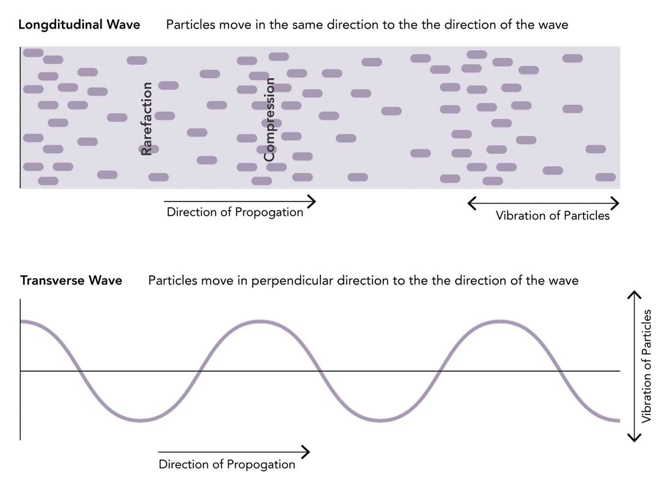
A form of mechanical energy transmitted as a pressure wave through a given medium by the vibration of molecules. It is transmitted as a longitudinal wave, made up of molecules oscillating in the direction of propagation
- Longitudinal waves create compressions and rarefactions within the air
- The alternating configuration of compressions (crests) and rarefactions (troughs) can be plotted on a graph as a sine wave
What is ultrasound?
High-frequency sound waves greater than 20 kHz
- Medical ultrasound uses waves of very high frequency, in the range of 2-20 MHz
- The human audible range is 20-20,000 Hz
Wave Properties
What are the key properties of a sound wave and how are they defined?
There are several important characterising properties of sound waves to be aware of:
or
Meters (m)
or
Meters (m)
or
Second (s)
or
Millimeters per microsecond (mm/msecond)
What is the relationship between wave frequency & wavelength?
- Frequency and wavelength are inversely related
- A short wavelength has more cycles per second and hence is a higher frequency
What is the velocity of a wave?
- Velocity (propagation speed) is the speed through a given medium
- It is determined solely by the characteristics of the medium:
- It does not depend on the source of sound or its frequency
- The density and compressibility of a medium are the key determinants
What is the velocity of ultrasound through body tissues?
- Each body tissue has a unique velocity determined by individual characteristics
- Machines commonly use an average value of 1,540 m/sec for soft tissue in depth calculations
What is acoustic impedance in relation to sound waves?
- Acoustic impedance (Z) is defined as:
The resistance to propagation of sound waves
- It is a physical property of the medium, which varies according to its density
- Can be calculated by the product of its density (p) and acoustic velocity (V).
Z = pV
What is the power of a wave?
- The power is the sum of the kinetic and potential energy in a wave
- Generally proportional to the amplitude squared and frequency squared
What is the intensity of a wave?
- Intensity varies throughout a diagnostic ultrasound beam
- It is highest at the centre of the beam, tapering off at the periphery
- It also varies along the path of the beam due to attenuation and focus
Principles
What is the piezoelectric effect?
- An effect exhibited by certain quartz crystals (such as lead zirconate titanates) known as ‘piezoelectric crystals’
- The piezoelectric crystal will change shape when an electrical potential is applied across it:
- Dimensions change slightly depending upon the polarity of the applied voltage
- Change in shape causes local changes in pressure, leading to mechanical waves (ultrasonic radiation) being generated at the exact frequency of the applied voltage
- The converse effect occurs when pressure is applied to a piezoelectric crystal:
- Compressive stress causes a change in dimensions of the crystal
- Generates an output voltage at the frequency of the compressive waves
- Allows piezoelectric crystals to act as transducers:
- Direct effect converts mechanical energy into electrical energy
- Converse effect converts electrical energy into mechanical energy
How are ultrasound images generated?
- Ultrasound waves are produced by an ultrasound probe:
- An electric current is passed through a piezoelectric crystal:
- Act as transducers converting electrical energy into mechanical vibrations at high frequencies
- Generates ultrasound waves at the frequency of the voltage applied
- Ultrasound waves travel through a given medium
- When a structure is encountered some waves are reflected back towards the probe
- The probe detects returning waves:
- The pressure effect distorts the piezoelectric crystals producing an output voltage
- Converts the mechanical energy into electrical energy
- Output signals from the probe are then converted into an image:
- The time between the waves being sent out and returning is calculated
- Depth of a structure is determined by the time taken for a wave to return
- Pixels are created at the appropriate depth for returning waves
- The brightness of the pixel correlates with the strength of returning wave
- Multiple crystals are located within a probe:
- Positioned adjacent to each other in an “array”
- Connected electrically to generate a 2D image
- As the ultrasound probe both emits and receives the signal they are known as ‘transceivers’.
Does the transducer produce ultrasound waves continuously?
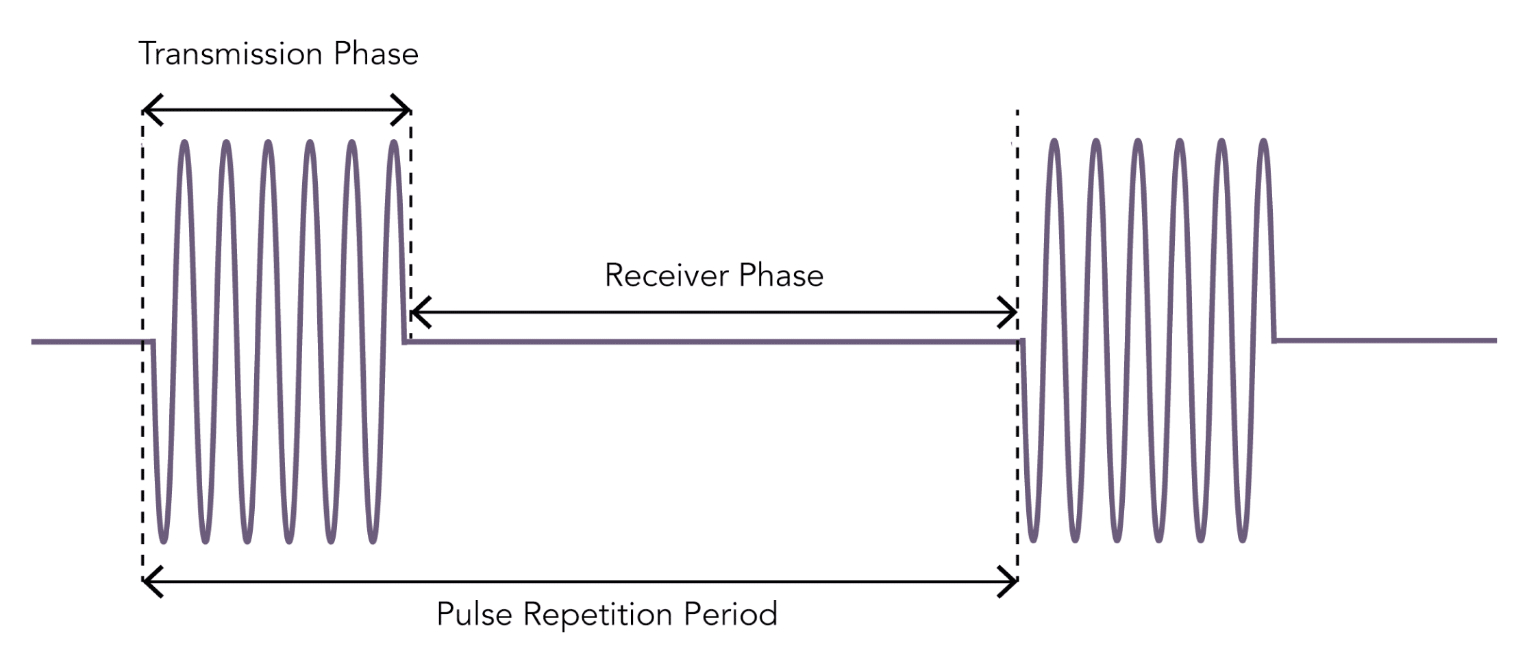
- The transducer alternates through phases of generating and receiving ultrasound waves
- The ‘Transmission Phase’ is the period of wave generation:
- Usually very brief (0.5–3 μs)
- Followed by a ‘Receiver Phase’ for wave detection:
- Much longer (up to 1 ms) than the transmission phase
- Allows echoes from a range of depths to be detected
- The combined duration of the transmission and receiver phases is the pulse repetition period:
- Determines the frame rate of an ultrasound generated image
- Shallower depths allows for a shortened receiver phase and thus a higher frame rate
Interaction With Tissue
What can happen to an ultrasound wave when it enters tissue?
- There are 3 possibilities when an ultrasound wave enters tissue:
- Ultrasound needs to be transmitted far enough into the tissues in order to image them but must be reflected back to be received by the probe
Why does reflection of ultrasound waves occur?
- Reflection occurs when waves encounter an interface or boundary between materials with different acoustic impedances
- The difference in impedance between mediums is known as the reflection coefficient
- The greater the reflection coefficient, the greater the size of the wave (and percentage of energy) that is reflected at the interface
- For example, a large difference in impedance is present between air and tissue:
- Therefore, almost all of the energy is reflected back towards the probe
- Almost no energy is transmitted through the air to allow image generation for deeper structures
- This explains why it is vital to use ultrasound gel when scanning to eliminate air tissue interfaces
- The angle of reflection of a wave equals the angle of incidence:
- When a wave strikes a tissue interface 90 degrees a very strong reflection travels back toward the ultrasound probe generating a bright image
- Waves striking tissue at other angles are reflected away from the probe leading to loss of wave energy
What is attenuation of ultrasound and which factors affect it?
- Attenuation can be defined as:
The net energy loss from the interaction of tissues with the ultrasound beam.
- This results in the amplitude and intensity of ultrasound waves decreasing as they travel through tissue
- Attenuation affects high-frequency ultrasound waves to a greater degree than lower frequency waves:
- Lower frequency transducers are used for scanning deeper structures
What are the mechanisms that cause attenuation?
- Due to 4 key mechanisms:
- Reflection away from the transducer when they come into contact with an interface at an angle other than 90°
- Bending of the ultrasound beam when a beam strikes an interface at an angle other than 90° causing it to deviate
- It is analogous to the appearance of a drinking straw bending when resting in a glass of water
- Dispersal of a beam when it strikes an interface that is the same size or smaller than its wavelength
- Absorbtion as heat, reducing the energy of the beam
- Degree of absorption is directly proportional to frequency
How is ultrasound attenuated in various tissues?
- Different tissues attenuate ultrasound waves dramatically differently
- Results in different abilities to transmit sound
- Often represented by the depth at which the energy of the sound wave has been halved – the “half-power distance”
- Significant attenuation through bone and air explains why ultrasound is poor at visualising these tissues
- The degree of attenuation through muscle explains why transoesophageal echocardiography can produce superior images to transthoracic echocardiography
How does the machine correct for attenuation?
- Attenuation means that weaker signals are received from deeper structures as compared to identical structures positioned more superficially
- Time-gain compensation (TGC) is an adjustment that ultrasound machines perform to differentially amplify signals depending on the depth they were received from.
Penetration & Resolution
What is resolution in ultrasound?
- Resolution can be defined as:
The detail of the image determined by the ability to distinguish two points as separate in space
- Two components of resolution can be considered:
Which factors affect ultrasound resolution?
- ‘Spatial pulse length’ is the product of the wavelength and the number of cycles in a pulse
- A shorter wavelength (and thus higher frequency) results in a shorter spatial pulse length
- Resolution is determined by the ‘spatial pulse length’ of the wave
- The minimum distance that can be reflected between two points is equal to half the ‘spatial pulse length’
- Therefore Resolution is high when the ‘spatial pulse length’ is short and the wave frequency is high
- Higher frequency waves have a greater resolution but at the expense of deeper penetration
Which factors affect ultrasound penetration?
- The absorption of an ultrasound wave is proportional to the frequency
- When more energy is absorbed the wave is less able to penetrate deep into tissues
- Therefore lower frequency waves penetrate deeper but at the expense of resolution
Artefacts
What is an ultrasound artefact?
- Artefact can be defined as:
An appearance that does not accurately correspond to the true image of the examined area
- Artefacts can often be recognized by altering the image plane, depth, or frequency
- An unusual object should be viewed from multiple directions to ensure that it is anatomic rather than artefactual
What types of ultrasound artefact can occur?
- Reverberation
- Comet Tail
- Mirror Image
- Acoustic Enhancement
- Acoustic Shadowing
- Refraction
- Side lobe
- Beam width
- Unshielded Electrical Equipment
- Aliasing
- Click
- Pacemakers
- Implants
- Contact / Interface
- Anatomic / Pitfall error
What acoustic artefacts can occur with ultrasound and what causes them?
- Beam reflected between two highly reflective interfaces
- Causes the same interface to be represented multiple times in the image at equally spaced positions
- Each representation is weaker and deeper due to the greater time it takes for the wave to return and the energy lost
- Interaction of waves with a strong reflector
- Gives the appearance of two images - one real and one artifact
- The artefactual image always appears deeper than the true anatomy and is an equal distance on the other side from the strong reflector
- Waves pass more easily through a fluid filled structures with only a minimal amount of the beam attenuated
- Leaves greater wave energy to be reflected after the fluid filled structure which appears brighter in the image due to time gain compensation
- Wave is unable to pass through a structure which is deep to a highly reflective surface
- Leaves a dark shadow behind where no waves are being reflected back to the transducer
- Refraction at the curved edge of a structure
- Causes the beam to be directed away from the probe at the edges and are therefore 'lost' from the image
- Beam contains waves fanning out from the apparently infinitely thin central beam which forms the main image.
- If a strong reflector is encountered in these side beams they can be reflected back and interpreted as part of the main image
- Beam is not equally wide along its course, having a narrower focal zone
- Artefact occurs when two structures in a wider part of the screen are displayed as overlapping when the machine displays reflections
Modes
Which imaging modes can be used with ultrasound?
(Amplitude Mode)
- Simplest form of imaging using a single wave emitted from the probe
- Scans a line through the body with echoes plotted as a function of depth
- Rarely used in intensive care or anaesthesia
- Used by ophthalmologists to measure the diameter of the eyeball
(Brightness Mode)
- The most commonly used mode in anaesthesia and intensive care
- Uses a linear array of transducers to produce a line of ultrasound waves
- Ultrasound scans through a section of tissue and is reflected back producing a two-dimensional view
- The intensity of the image generated is proportional to the intensity of reflected echoes received
- Best image is produced when the reflector is at 90° to the ultrasound beam
(Motion Mode)
- Used to show how a structure moves temporally across a single beam of ultrasound
- Plots a rapid sequence of a-mode images over time
- Often used in cardiac or thoracic scanning to show the movement of structures (e.g. heart valve motion)
- Utilizes the doppler effect to detect the direction and velocity of flow
- Colour Flow Doppler: displays the direction and magnitude of flow with colour. Blue indicates flow Away from the ultrasound probe and Red indicates flow Towards the probe (BART)
- Duplex Doppler: combines real time color doppler superimposed onto real-time grey-scale b-mode image
Probes
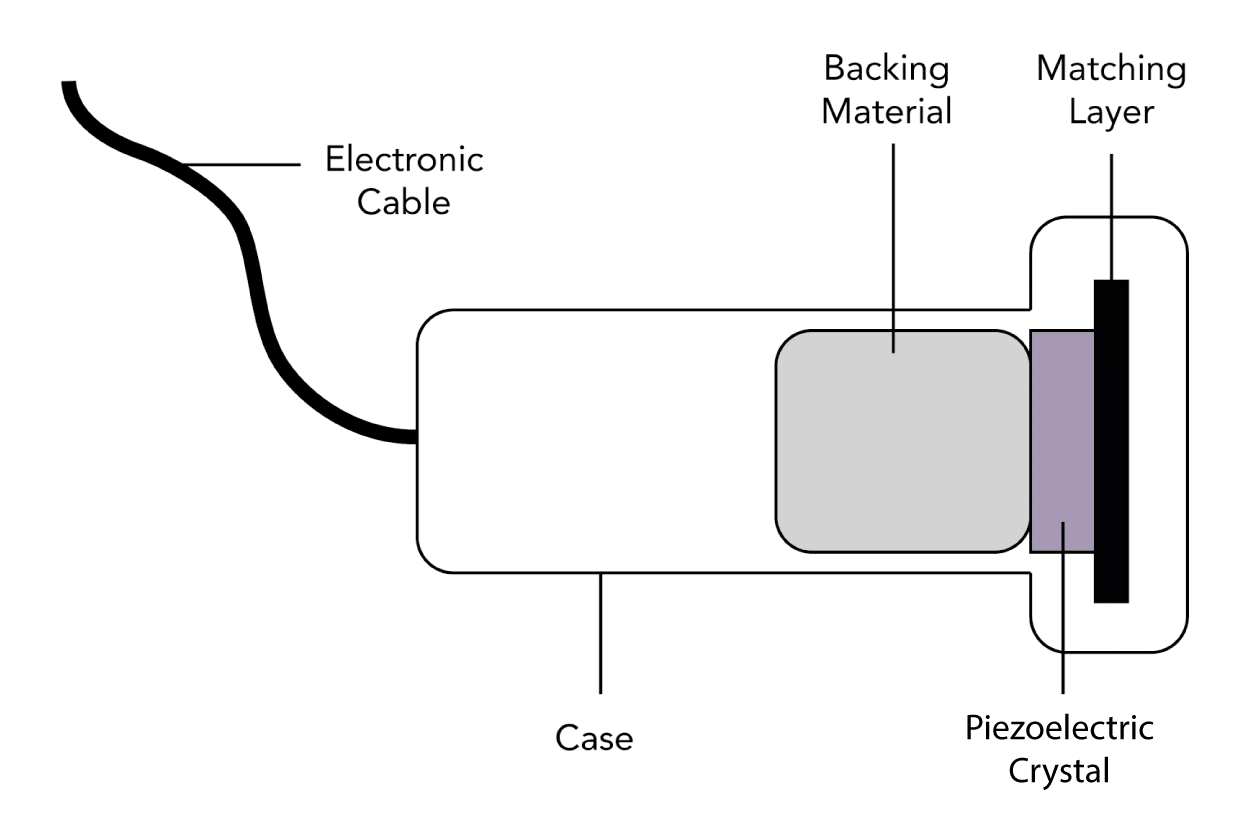
What is the structure of an ultrasound transducer?
What types of ultrasound probes are available?
- Probes can be characterized according to their:
- Shape
- Arrangement of the piezoelectric crystals
- Frequency range
- Footprint
- In general they are classified as:
- Crystals arranged in a linear fashion
- Flat rectangular footprint which produces a rectangular image
- Generally of high frequency (5-10 MHz) providing good resolution for shallow structures
- A "hockey stick" probe is a linear array probe with a small footprint for use in paediatrics or smaller anatomical areas
- Vascular access
- Superficial nerve blocks (supraclavicular and axillary brachial plexus, forearm, femoral etc.)
- Musculoskeletal imaging
- Pleural imaging
- Crystals arranged alongside each other across a curved face
- Produce a sector shaped image with a curved top and bottom
- Generally of lower frequencies (2–5 MHz), allowing for better imaging of deeper structures
- Abdominal and pelvic imaging
- Lung Imaging
- Deep nerve blocks (sciatic, infraclavicular brachial plexus etc.)
- Crystals arranged in a very small cluster
- Has a flat footprint which produces a pie-shaped image
- Generally of lower-frequency (2–8 MHz) allowing imaging of deeper structures
- Small footprint makes it useful for cardiac imaging between ribs
- Echocardiography
- Specialist probes with long handles to scan inside body cavities
- Common examples include: vaginal, anorectal, laparoscopic and oesophageal probes
- Internal imaging (transvaginal, transrectal etc.)
What are the benefits and uses of high and low-frequency ultrasound probes?
- 6-15 MHz range
- Good resolution (0.5 mm axial and 1.0 mm lateral)
- Reduced penetration (5-6 cm depth of field)
- 2-5 MHz typical range
- Good penetration (5-18 cm depth of field)
- Reduced resolution (2.0 mm axial and 3.0 mm lateral)
- Vascular access
- Superficial nerve blocks (supraclavicular and axillary brachial plexus, forearm, femoral etc)
- Musculoskeletal imaging
- Pleural evaluation
- Abdominal and pelvic imaging
- Lung Imaging
- Deep nerve blocks (sciatic, infraclavicular brachial plexus etc)
- Neuraxial structures
How can an ultrasound probe be manipulated to obtain an optimal image?
- Improves the image by reducing the distance to target structures through compression of subcutaneous tissues
- Can be used to compress veins or move structures out of the way
- Care needs to be taken not to use excessive pressure which causes discomfort for the patient
- Refers to the movement of the probe on the skin to move the target structure into the field of view
- Sliding the transducer through different alignments can be useful in tracing structures along their course to help with identification
- Refers to the twisting of the prove to fine tube the view of a target structure
- Allows the true axial view of structures to be obtained
- Rotation through 90° can change an image from a long axis to a short axis view
- Assists in bringing the face of the probe, and thus the direction of the ultrasound beam, into a perpendicular arrangement with the target structure
- This maximises waves reflected back to the probe and thus provides a better image
Optimisation
Which features on an ultrasound scanner can be changed to optimise the image?
- Describes the degree of amplification of the reflected signal that is received
- If low gain is used, tissues that are poor reflectors will not be visualised
- If high gain is used noise is added to the image and it can become difficult to delineate different structures
- The beam possesses a focal point where resolution is highest, much like a camera lens
- This is usually set to an area 2/3rds of the total depth
- The structure of interest should be positioned within the area of greatest focus
- Optimum depth should always be selected to allow visualisation of the structures without additional areas
- Shallower depth allows for a faster frame rate
- Describes the range between the minimum low and maximum high signal intensity that is displayed
- This equates to the contrast that is viewed within the image upon the screen
- Generally a high dynamic range is used to improve the image quality although it may need to be reduced in the presence of "noise"
- Selecting a narrower sector width allows a faster frame rate and increased resolution but with reduced field of view
- Can often be changed to increase the resolution depending upon the structures being imaged
Principles
What is the Doppler effect?
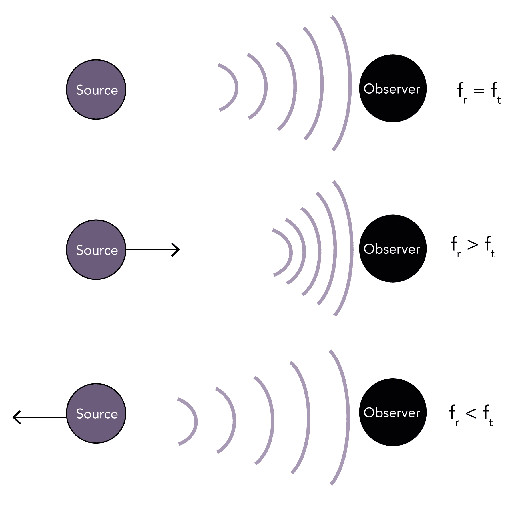
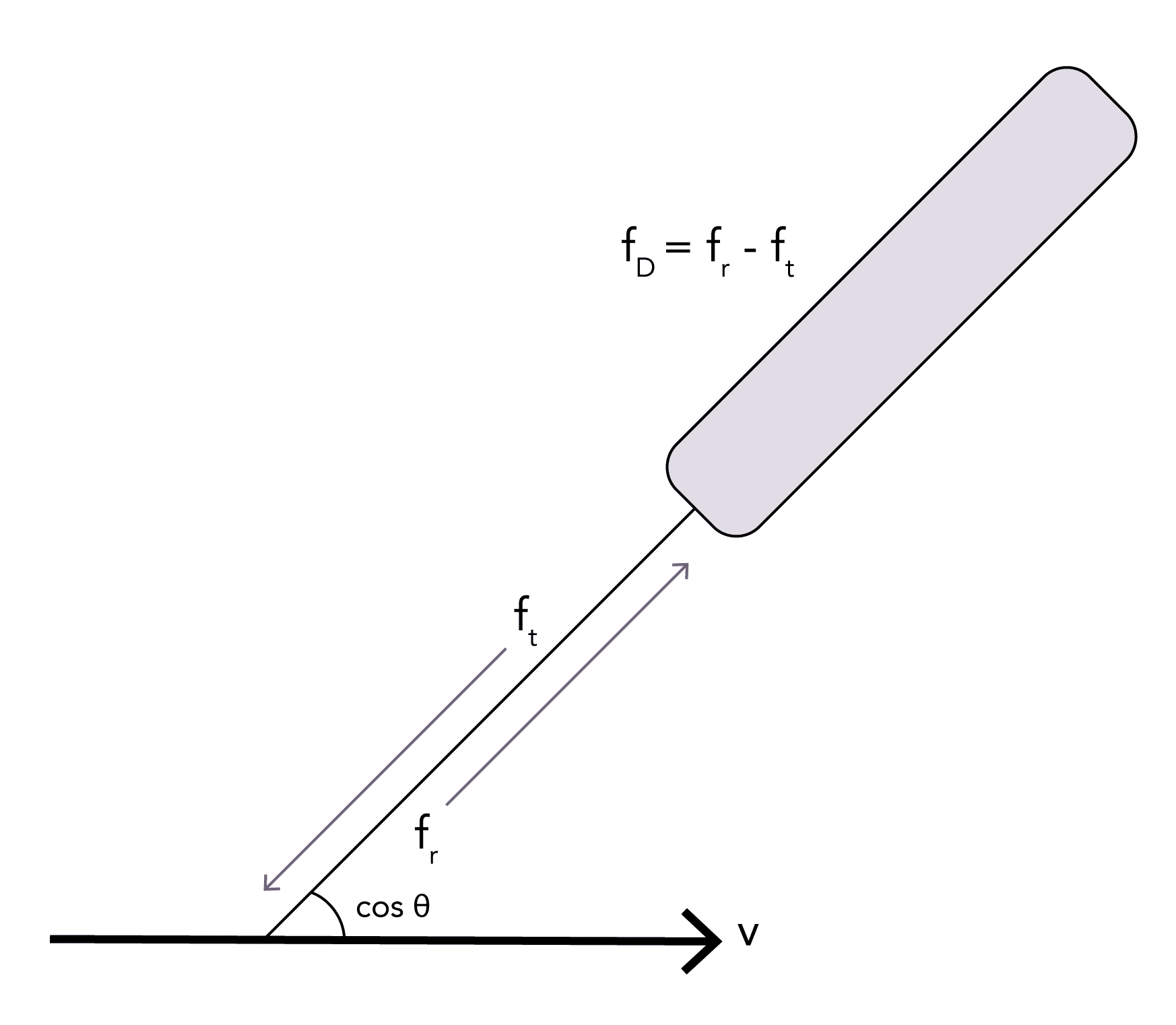
- Describes the change in the transmitted frequency of a sound wave (ft) compared to the reflected (observed) frequency of the wave (fr) that occurs due to the relative motion between the observer and the source
- If the source and the observer are stationary any waves reflected back will be of the same frequency (fr = ft)
- If the source is moving toward the observer it causes waves to be more closely packed together, so the observer witnesses a higher frequency wave (fr > ft)
- Conversely, if the source is moving away from the observer it causes waves to be more loosely packed together, so the observer witnesses a lower frequency wave (fr < ft)
- The change in the observed frequency from that originally transmitted is known as the ‘Doppler shift’ (fd = fr – ft)
- It is proportional to the relative velocity between the source and the observer
- It does not matter whether it is the source or the observer which is moving
- An example in everyday life is the change in pitch of a siren as a police car passes by
What is the Doppler equation?
c = the speed of sound in tissues (m/s)
fd = Doppler frequency shift that is received (Hz)
cos θ = cosine of the angle between the sound beam and moving fluid (45°)
fT = frequency of the transmitted ultrasound from the transducer (Hz)
Clinical Application
What is the doppler effect used for clinically?
- Oesophageal doppler cardiac output monitoring
- Transcranial doppler monitoring of cerebral blood flow
- Echocardiography:
- Assessment of cardiac output
- Assessment of valvular dysfunction
- Assessment of diastolic dysfunction
- Assessment of pulmonary artery pressures
- Imaging of vessel patency and flow:
- Detection of arterial or venous thromboses
- Assessment of portal venous flow
- Assessment of renal blood flow
What are the types of doppler imaging available?
- Dispays velocity information detected from a single location in the form of a frequency shift– time plot
- The vertical distance from the baseline corresponds to Doppler shift
- The greyscale indicates the amplitude of the detected ultrasound of a particular frequency
- Displays the direction and magnitude of flow as a colour image
- Blue indicates flow Away from the ultrasound probe and Red indicates flow Towards the probe (BART)
- Combines real time color doppler superimposed onto real-time grey-scale b-mode image
Overview
What is ultrasound used for in anaesthesia and intensive care?
- Vascular access
- Peripheral nerve blockade
- Pleural / peritoneal / pericardial aspiration or drainage
- Assessment prior to Neuraxial blockade
- Assessment of cricothyroid membrane prior to cannulation
- Echocardiography:
- Transthoracic
- Transoesophageal
- 'Point of Care Ultrasound':
- Lung imaging
- Abdominal imaging & detection of portal venous flow*
- Trauma Imaging (FAST Scan)
- Detection of DVT*
- Oesophageal doppler cardiac output monitoring*
- Transcranial doppler assessment of cerebral blood flow*
- Foetal heart rate monitoring
- Cleaning of equipment
- Humidification devices
- Therapy for acute and chronic pain
* Uses Doppler
What are the advantages and disadvantages of ultrasound imaging?
- Relatively inexpensive
- Widely available
- Can be performed by the bedside
- Non-invasive
- Non-ionising
- Safe in children and pregnancy
- Operator dependent
- Cannot image lung or bone
- Not good for imaging obese patients or deep structures
- Specific issues with oesophageal probes:
- Contraindicated in patients with strictures or tumours
- Carry risk of bleeding (particularly in varices) or perforation

