Home » EDEC » 1. Image Acquisition & Interpretation » EDEC TTE Protocol

Parasternal Long Axis (PLAX) Views

Transducer
Description
Example
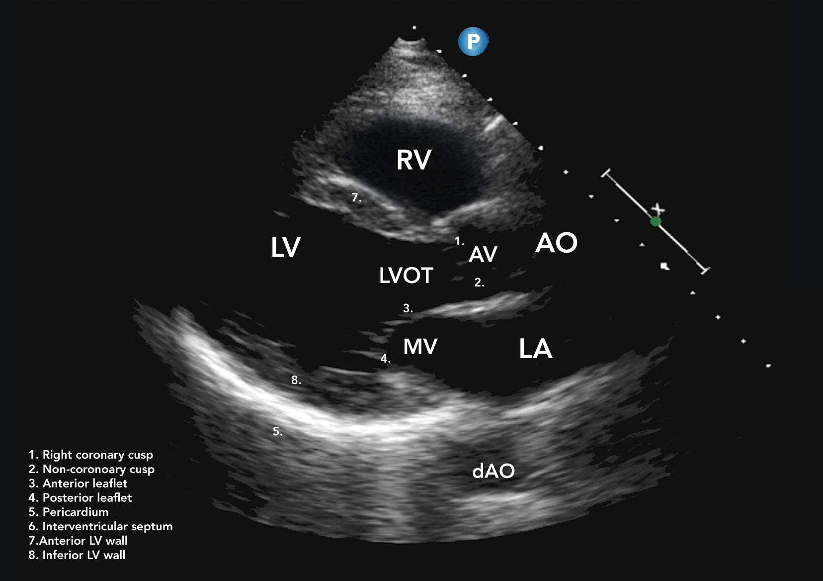
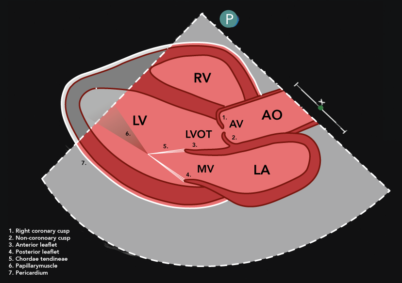
Anatomy

PLAX Increased Depth

Placed in the third or fourth intercostal space to the left of the sternum, with the index marker pointed to the patient’s right shoulder at approximately the 9 to 10 o’clock position.
If possible, the left ventricle should appear positioned perpendicular to the ultrasound beam within the image sector. If the ventricle does not appear relatively horizontal, the transducer may be moved to a higher parasternal window or the patient turned to a steeper left lateral decubitus position. In a majority of patients, the apex should not be seen in the PLAX view. The appearance of a ‘‘false apex’’ and a short left ventricle may be eliminated by rotating, tilting, and/or angling the transducer, thus maximizing the LV cavity length within the field of view.

Visual Assessment

  • Pleural space
  • Pericardial space
Transducer
Description
Example
Anatomy

PLAX Left Ventricle

Placed in the third or fourth intercostal space to the left of the sternum, with the index marker pointed to the patient’s right shoulder at approximately the 9 to 10 o’clock position.
As per PLAX increased depth. Depth altered to show around 1cm below the pleural line.
Description
Image

Visual Assessment

  • Global LV function
  • Regional wall motion
Qualitative assessment of radial function and motion of the anterior septum and inferior lateral walls:
  • BAS: Basal antero-septum
  • MAS: Mid antero-septum
  • BIL: Basal infero-lateral
  • MIL: Mid infero-lateral
  • Pcture 1

    2D Measurement

      In end-diastole

    • Intraventricular septum diameter (IVSd)
    • Left ventricle end-diastolic diameter (LVEDd)
    • Left ventricle posterior wall diameter (LVPWd)
    • In end-systole:

    • Left ventricle end-diastolic diameter (LVESd)
    • Performed in end-diastole and end-systole.
    • Measurements are made at the same level, perpendicular to the long-axis plane of the LV and immediately below the mitral valve leaflet tips.
    • Ensure that the measurement is of compacted myocardium only and that trabeculation / valve apparatus avoided.
    • When present, measure distal (more apical) to the septal bulge.
    Picture 1

    2D Measurement

      In end-systole

    • Left atrial diameter (LAd)
    • Inner edge to inner edge method is used at end-systole.
    • Measure perpendicular to the aortic root and at the level of the sinus of Valsalva.Inner edge to inner edge method is used at end-systole.
    • M-mode measurement not recommended due to risk of oblique measurement.
    Picture 1

    2D Measurement

      In end-diastole

    • Right ventricular outflow tract diameter (RVOTd)
    • Adjust depth and focal zone to visualise the RVOT.
    • Inner edge to inner edge method is used at end-diastole.
    • Measure using a perpendicular line from the RVOT wall to the junction between the interventricular septum and aortic valve.
    Picture 1

    M-Mode Measurement

    • Fractional shortening
    Transducer
    Description
    Example
    Anatomy

    PLAX Mitral Valve (+/- Zoom)

    Placed in the third or fourth intercostal space to the left of the sternum, with the index marker pointed to the patient’s right shoulder at approximately the 9 to 10 o’clock position.
    Focus and zoom on the mitral valve. Standard PLAX plane demonstrates MV scallops A2 and P2 (anterior leaflet leading to the AV, posterior leaflet extending from the base of the infero-lateral wall). Tilting view towards the RV inflow view demonstrates scallops A3 and P3. Tilting the probe towards the RV outflow view will demonstrate scallops A1 and P1.
    Description
    Image

    Visual Assessment

    • Mitral valve morphology
    Qualitative assessment of leaflet anatomy and motion.
    Pcture 1

    M-Mode Measurement

    • Assessment of valve excursion
    • E-point septal separation (EPSS)
  • Demonstrate timing and speed of leaflet excursion
  • Measure smallest point between E-wave of the mitral valve and the ventricular wall
  • M-Mode Measurement

    • Mitral Regurgitant jet
    • M-mode assessment of timing of regurgitant jet
    • Optimise colour flow Doppler (CFD) settings.
    • Adjust the lateral CFD region of interest (ROI) to include 1 cm of the LV on the left lateral border and the roof of the LA on the right lateral border. Height should not extend beyond the anterior and posterior LA walls.
    Picture 1
    Transducer
    Description
    Example
    Anatomy

    PLAX Aortic Valve (+/- Zoom)

    Placed in the third or fourth intercostal space to the left of the sternum, with the index marker pointed to the patient’s right shoulder at approximately the 9 to 10 o’clock position.
    As per PLAX increased depth. Depth altered to show around 1cm below the pleural line.
    Description
    Image

    Visual Assessment

    • Mitral valve morphology
    Qualitative assessment of leaflet anatomy and motion.
    Pcture 1

    M-Mode Measurement

    • Assessment of valve excursion
    • E-point septal separation (EPSS)
  • Demonstrate timing and speed of leaflet excursion
  • Measure smallest point between E-wave of the mitral valve and the ventricular wall
  • M-Mode Measurement

    • Mitral Regurgitant jet
    • M-mode assessment of timing of regurgitant jet
    • Optimise colour flow Doppler (CFD) settings.
    • Adjust the lateral CFD region of interest (ROI) to include 1 cm of the LV on the left lateral border and the roof of the LA on the right lateral border. Height should not extend beyond the anterior and posterior LA walls.
    Picture 1
    Transducer
    Description
    Example
    Anatomy

    PLAX Right Ventricle Inflow

    Placed in the third or fourth intercostal space to the left of the sternum, with the index marker pointed to the patient’s right shoulder at approximately the 9 to 10 o’clock position.
    As per PLAX increased depth. Depth altered to show around 1cm below the pleural line.
    Description
    Image

    Visual Assessment

    • Mitral valve morphology
    Qualitative assessment of leaflet anatomy and motion.
    Pcture 1

    M-Mode Measurement

    • Assessment of valve excursion
    • E-point septal separation (EPSS)
  • Demonstrate timing and speed of leaflet excursion
  • Measure smallest point between E-wave of the mitral valve and the ventricular wall
  • M-Mode Measurement

    • Mitral Regurgitant jet
    • M-mode assessment of timing of regurgitant jet
    • Optimise colour flow Doppler (CFD) settings.
    • Adjust the lateral CFD region of interest (ROI) to include 1 cm of the LV on the left lateral border and the roof of the LA on the right lateral border. Height should not extend beyond the anterior and posterior LA walls.
    Picture 1
    Transducer
    Description
    Example
    Anatomy

    PLAX Right Ventricle Outflow

    Placed in the third or fourth intercostal space to the left of the sternum, with the index marker pointed to the patient’s right shoulder at approximately the 9 to 10 o’clock position.
    As per PLAX increased depth. Depth altered to show around 1cm below the pleural line.
    Description
    Image

    Visual Assessment

    • Mitral valve morphology
    Qualitative assessment of leaflet anatomy and motion.
    Pcture 1

    M-Mode Measurement

    • Assessment of valve excursion
    • E-point septal separation (EPSS)
  • Demonstrate timing and speed of leaflet excursion
  • Measure smallest point between E-wave of the mitral valve and the ventricular wall
  • M-Mode Measurement

    • Mitral Regurgitant jet
    • M-mode assessment of timing of regurgitant jet
    • Optimise colour flow Doppler (CFD) settings.
    • Adjust the lateral CFD region of interest (ROI) to include 1 cm of the LV on the left lateral border and the roof of the LA on the right lateral border. Height should not extend beyond the anterior and posterior LA walls.
    Picture 1

    Parasternal Short Axis (PSAX) Views

    Transducer
    Description
    Example
    Anatomy

    PSAX Outflow

    Placed in the third or fourth intercostal space to the left of the sternum, with the index marker pointed to the patient’s right shoulder at approximately the 9 to 10 o’clock position.
    As per PLAX increased depth. Depth altered to show around 1cm below the pleural line.
    Description
    Image

    Visual Assessment

    • Mitral valve morphology
    Qualitative assessment of leaflet anatomy and motion.
    Pcture 1

    M-Mode Measurement

    • Assessment of valve excursion
    • E-point septal separation (EPSS)
  • Demonstrate timing and speed of leaflet excursion
  • Measure smallest point between E-wave of the mitral valve and the ventricular wall
  • M-Mode Measurement

    • Mitral Regurgitant jet
    • M-mode assessment of timing of regurgitant jet
    • Optimise colour flow Doppler (CFD) settings.
    • Adjust the lateral CFD region of interest (ROI) to include 1 cm of the LV on the left lateral border and the roof of the LA on the right lateral border. Height should not extend beyond the anterior and posterior LA walls.
    Picture 1
    Transducer
    Description
    Example
    Anatomy

    PSAX AV Zoomed

    Placed in the third or fourth intercostal space to the left of the sternum, with the index marker pointed to the patient’s right shoulder at approximately the 9 to 10 o’clock position.
    As per PLAX increased depth. Depth altered to show around 1cm below the pleural line.
    Description
    Image

    Visual Assessment

    • Mitral valve morphology
    Qualitative assessment of leaflet anatomy and motion.
    Pcture 1

    M-Mode Measurement

    • Assessment of valve excursion
    • E-point septal separation (EPSS)
  • Demonstrate timing and speed of leaflet excursion
  • Measure smallest point between E-wave of the mitral valve and the ventricular wall
  • M-Mode Measurement

    • Mitral Regurgitant jet
    • M-mode assessment of timing of regurgitant jet
    • Optimise colour flow Doppler (CFD) settings.
    • Adjust the lateral CFD region of interest (ROI) to include 1 cm of the LV on the left lateral border and the roof of the LA on the right lateral border. Height should not extend beyond the anterior and posterior LA walls.
    Picture 1
    Transducer
    Description
    Example
    Anatomy

    PSAX RVOT

    Placed in the third or fourth intercostal space to the left of the sternum, with the index marker pointed to the patient’s right shoulder at approximately the 9 to 10 o’clock position.
    As per PLAX increased depth. Depth altered to show around 1cm below the pleural line.
    Description
    Image

    Visual Assessment

    • Mitral valve morphology
    Qualitative assessment of leaflet anatomy and motion.
    Pcture 1

    M-Mode Measurement

    • Assessment of valve excursion
    • E-point septal separation (EPSS)
  • Demonstrate timing and speed of leaflet excursion
  • Measure smallest point between E-wave of the mitral valve and the ventricular wall
  • M-Mode Measurement

    • Mitral Regurgitant jet
    • M-mode assessment of timing of regurgitant jet
    • Optimise colour flow Doppler (CFD) settings.
    • Adjust the lateral CFD region of interest (ROI) to include 1 cm of the LV on the left lateral border and the roof of the LA on the right lateral border. Height should not extend beyond the anterior and posterior LA walls.
    Picture 1
    Transducer
    Description
    Example
    Anatomy

    PSAX IAS

    Placed in the third or fourth intercostal space to the left of the sternum, with the index marker pointed to the patient’s right shoulder at approximately the 9 to 10 o’clock position.
    As per PLAX increased depth. Depth altered to show around 1cm below the pleural line.
    Description
    Image

    Visual Assessment

    • Mitral valve morphology
    Qualitative assessment of leaflet anatomy and motion.
    Pcture 1

    M-Mode Measurement

    • Assessment of valve excursion
    • E-point septal separation (EPSS)
  • Demonstrate timing and speed of leaflet excursion
  • Measure smallest point between E-wave of the mitral valve and the ventricular wall
  • M-Mode Measurement

    • Mitral Regurgitant jet
    • M-mode assessment of timing of regurgitant jet
    • Optimise colour flow Doppler (CFD) settings.
    • Adjust the lateral CFD region of interest (ROI) to include 1 cm of the LV on the left lateral border and the roof of the LA on the right lateral border. Height should not extend beyond the anterior and posterior LA walls.
    Picture 1